 |
 |
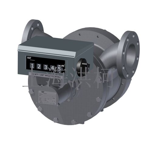
名称:MILLIFLOW流量计。高精度VAF 4活塞式流量计可测量低粘度和高粘度以及侵蚀性液体,流量额定值为1至20升/小时,压力可达100bar。入口和出口路径不是必需的。过滤器是必需的。除其他应用外,典型的应用还有燃料的添加,添加剂,胶水和抑制剂的添加量。这些精密测量设备适用于工业以及实验室或试验台应用。
|
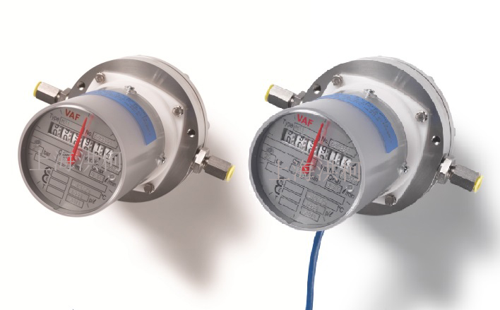
高精度VAF叶片流量计可测量液体,从液态气体到高压粘度高达52bar的高粘度范围。入口和出口路径不是必需的。过滤器是必需的。除了其他应用之外的典型应用是添加剂,胶水和抑制剂的剂量。这些精密测量设备显示出低压降,适用于工业和试验台应用。
如果您需要报价或想订购,请联系我们的顾问。
型号 J1010 J1015
J3010 J3015 (J3023)
介质 liquids with particles of less than 50 microns size
口径 DN10 DN15
流量范围 1 – 20l/min 2,5 – 50l/min
精度 ±0,3%
材质 钢, 不锈钢316
温度范围 -15 to +200°C
压力 可达52bar
接口 脉冲,计数器,仪表,可选4..20mA
证书 防爆证书, 校准证书 |
 |
 |
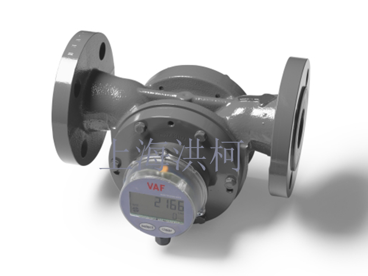
高精度VAF叶片式流量计可测量压力高达40巴的各种粘度范围内的液体。入口和出口路径不是必需的。过滤器是必需的。球墨铸铁底盘仅适用于非腐蚀性介质。一个典型的应用领域是石化行业。这些精密测量设备具有低压降,适用于工业以及测试台应用。
高粘度模型
液态气体模型 |
 |
 |
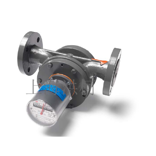
高精度VAF叶片式流量计测量压力高达16巴时的各种粘度范围内的液体。入口和出口路径不是必需的。过滤器是必需的。Hi流量叶片仪表采用石墨铸铁,钢和不锈钢制成。典型的应用领域除了化学和石油化工行业的测量和运输任务外。这些精密测量装置具有低压降,适用于恶劣条件下的工业应
型号
J5150 J5200 J5250 J5300
J1150 J1200 J1250 J1300
J3150 J3200 J3250 J3300
介质:液体颗粒尺寸小于100/250微米
口径:DN150 DN200 DN250 DN300
流量范围:200 – 4600l/min;300 – 8000l/min;500–12500l/min;700 – 16000l/min
精度:±0,3%
材质:石墨铸铁J50XX,钢J10XX,不锈钢J30XX
温度范围:-15 to +200°C
压力:可达16bar
接口:脉冲,计数器,仪表,可选4..20mA
证书:防爆证书, 校准证书
选项:使用蒸汽或油加热盖子
高粘度模型 |
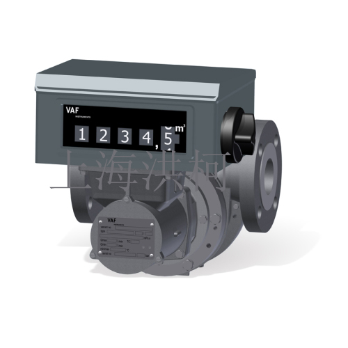
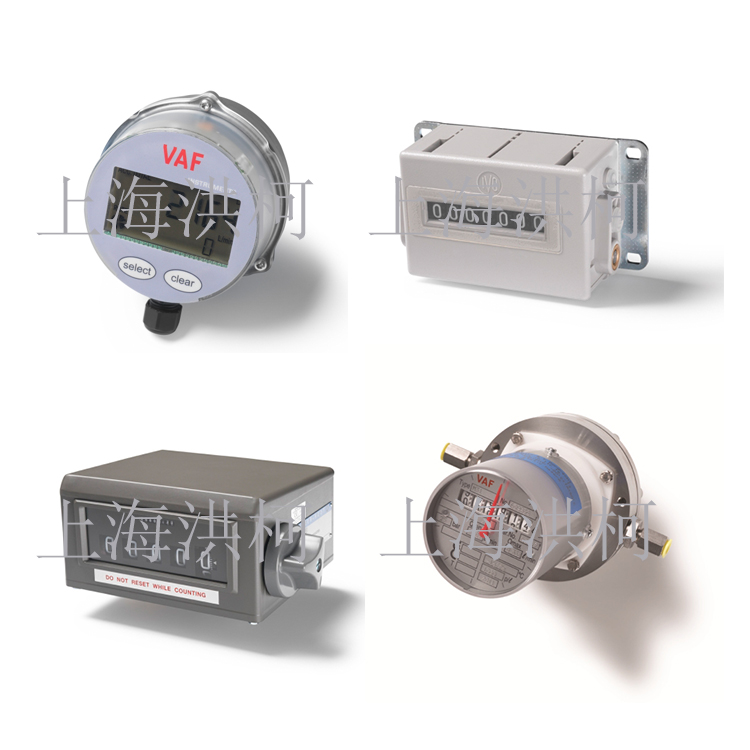
不同的累加器可以基于VAF叶片仪表。提供可重置的机械式环流仪的手册和方便的流量和可复位总量的电子显示屏。所有累加器都配有4-20mA接口,适用于爆炸性环境。机械装置适用于工业环境中的稳健使用。
| 型号 |
VEEDER ROOT
VR1 |
VEEDER ROOT
VR2 |
Flow Count
E200 |
N Counter
N |
VAF COUNT
C |
| 计数器 |
机械式 |
机械式 |
电子式 |
机械式 |
电子式 |
| 显示 |
7位数 |
5位数 |
7位数 |
6位数 |
7位数 |
| 单位 |
升
加仑 |
升 立方米
加仑 |
升
加仑 |
升
加仑 |
升
加仑 |
| 复零 |
按键 |
手动 |
手动 |
不可 |
手动 |
| 选项 |
- |
泛适配器可扩展计数器 |
批量计数器 |
- |
- |
| 适用流量计 |
MidFlow
HighFlow |
MidFlow
HighFlow |
MilliFlow
LoFlow
ProFlow |
MilliFlow
LoFlow
ProFlow |
LoFlow
ProFlow |
| 重量 |
1kg |
7kg |
0.5kg |
0.8kg |
0.5kg |
|
 |
 |
这些机械计数器可以安装在J系列VAF叶片式流量计上。不需要电源。 简单,可手动复位的循环仪寄存器,配有方便的批量计数器,用于对截止阀进行机械,电气或气动控制。 批量可以使用机械收据打印机进行记录。 除其他应用外,典型的应用是化工和石化行业的运输任务。 这些器件适用于工业环境中的强大应用。
型号 VEEDER ROOT
VR3
计数器 机械
显示 5位数字
单位 升, 立方米, 加仑
Reset manual
选项 计数器扩展
To be combined with MidFlow
HighFlow
重量 21kg |
///////////////////////////////// |
 |
 |
| ///////////////////////////// |
///////////////////////////// |
□荷兰VAF INSTRIMENTS容积式流量计须知
Technical Manual 技术手册
Instructions for installation, operation and maintenance
安装操作和维护指南
761
VISCOSENSE.2
Viscosity Sensor & Interface box
扭转振动式黏度传感器及界面盒
Valid for ViscoSense.2 (serial number from 87600)
本手册适用于序列号87600 以上之传感器
To ensure safe and correct installation and operation, read this manual completely before installing the equipment and starting operations.
为确保安装操作的正确进行,请在动手前完整详细地阅读本手册。
ViscoSense.2 sensor (from serial numbers 70000) and interface box (from serial numbers 1480000) are not interchangeable with previous model ViscoSense.. 新型号ViscoSense.2 之探头(序列号70000以上)及界面盒(序列号1480000以上)与此前使用的型号ViscoSense..不可进行互换。
The following symbols are used to call attention to specific types of information. 下列符号提示引起注意
A warning to use caution! In some instances, personal injury or damage to the ViscoSense.2unit or control system may result if these instructions are not followed properly.
小心警告!违规操作会导致人员伤亡或测量仪损坏。
An explanation or information of interest.
对相关情况的解释或注解
COPYRIGHT 版权
This technical manual is copyrighted with all rights reserved. 本手册版权所有While every precaution has been taken in the preparation of this manual, no responsibility for errors or omissions is assumed. Neither is any liability assumed for damages resulting from the use of the information contained herein. Specifications can be changed without notice.
虽然我们在编撰出版本手册时已采取各种防范措施,但仍难免会出现误差等。我们对由此可能引起的损失不承担任何责任。同时我们有权随时更改本手册。ViscoSense. is a registered trademark of VAF Instruments B.V. ViscoSense. 是VAF公司的注册商标Teflon. is a registered trademark of Dupont. 特富龙. 是杜邦公司的注册商标
2 SYSTEM DESCRIPTION 系统描述
2.1 SYSTEM DESCRIPTION 系统概述ViscoSense.2 is, besides other applications, intended for use in fuel oil treatment systems to obtain
a correct measurement and control of the fuel oil viscosity. 扭转振动黏度计ViscoSense.2 既是应用于燃油处理系统以期对燃油的粘度进行准确测量及调控
Figure 1 shows a typical fuel treatment system with return line from the engine. In this system, the degassing/mixing tank operates as a fuel buffer, ensuring gradual changes of viscosity which results in a stable control of the viscosity. The ViscoSense.2 sensor is used to measure the actual viscosity of the fuel oil. The signal from the sensor is compared to the setpoint of a viscosity controller, which regulates the output of the fuel heater via a control element (steam or thermal oil valve, or electric heater cabinet).
Figure 1 Typical example of an automatic control system using steam or thermal oil heater
图表1给出了一个典型的具有主机回流管路的燃油处理系统图。在该系统中,除去瓦斯/混油桶起到燃料缓冲器的作用以确保黏度渐变,从而获得对黏度的稳定控制。控制系统对黏度传感器发出的信号与控制器的设定值进行比较,通过控制元件[蒸汽,热油阀或电热器]以调节加热器的输出
Marine Diesel Oil 船用柴油Heavy Fuel Oil 重燃油Feeder Pump 供给泵Degassing/Mixing Tank 除去瓦斯/混油桶Filter 过滤器Booster Pump 增压推进泵Fuel Heater 燃油加热器Steam/Oil 蒸汽/油Control Element 控制元件Controller 黏度控制器ViscoSense. Sensor 探头ViscoSense. Interface Box 界面接口盒Engine 发动机
SYSTEM COMPONENTS 系统组成部分
The ViscoSense.2 viscosity system consists of: 扭转振动黏度测量系统包括.the combined viscosity and temperature measuring sensor 黏度及温度测量传感器.the sensor housing 传感器安放室. Interface box 界面盒
The sensor housing is made of ductile iron and has flanges for direct mounting in the fuel line. The sensor itself is made of stainless steel and is mounted in the housing. The sensor head has a special Teflon. coating and it is mechanically protected by a stainless steel flowtube with 3 oval slits. It is supplied with 5 metres of signal cable for connection to the interface box. The ViscoSense.2 Interface box is a wall mount electronic unit, processing the signals from and to the sensor. It provides 4..20 mA signals for remote read-out of viscosity and temperature for a controller or other system elements. See separate technical manuals for a description of these components.
传感器安放仓室由球墨铸铁制成,其两侧连接法兰便于直接在管路中安装。传感器本身由不锈钢制成,安放在仓室中。传感器探头的表面经过特富龙.特殊处理,并且受到其上有三个椭圆形开口的不锈钢流管的机械保护。传感器自带5米长的信号电缆用于与界面接口盒之间联接。第二代ViscoSense. 传感器界面盒系壁式安放电子装置,加工处理来自及传送至传感器的信号。输出4-20mA 电流信号用于控制器或其他系统组件远程温度黏度显示。请分别参阅这些部分的专门技术手册。
Housing 探头安放仓室
Flow 流动
ViscoSense Sensor 探头
Cable Length ± 5 Meters 连接缆线长度约5米
ViscoSense Interface Box 界面接口盒
Figure 2 ViscoSense.2 components 图2 传感器组件
PRINCIPLE OF OPERATION 操作原理The patented measuring principle is based on rotational vibration of a pendulum in liquid.
已获得专利权的测量原理系以传感器探头在流体中的旋转振动为基础
The sensor consists of a sensor head (1) attached to a base plate (2) by a torsion tube (3). Two sets of piezo-electric elements (4) are positioned inside the pendulum. One set drives the pendulum, the other set measures and controls the rotational movement of the pendulum via a feedback circuit. In this way the pendulum is kept in vibration at its resonance frequency. 传感器系由通过扭管(3)固定在基座(2)上的钟摆(1)组成。钟摆内置两套压电陶瓷元件(4)。一套驱动钟
摆,而另一套通过反馈信号测量和控制钟摆的旋转动作。这样使钟摆在其共振频率上保持振动。
Measuring the resulting frequency at two specific values of phase difference, yields a value for the damping which is proportional to the square root of the dynamic viscosity.
测量相位差两点的频率,得出衰减值。这一数值与动力黏度的平方根成正比。
A flow tube (5) is placed around the pendulum, to protect it against mechanical damage. 流管(5)被置于钟摆外围,以保护钟摆避免机械损坏。The flowtube is machined with a smooth surface, as well as with a triplet of oval slits. These slits
increase the refreshing rate between sensor and flowtube.
流管经过精细机加工处理,表面光滑并有三个椭圆形开口。这些开口增加了传感器探头和流管之间的更新速率。
Figure 3 ViscoSense.2 sensor 图3 扭转振动传感器探头
3 TECHNICAL SPECIFICATION 技术规格
3.1 SENSOR 传感器
Viscosity range 粘度量程0 .. 25/50 mPa.s 毫米帕斯卡·秒
(other ranges on request 其它粘度量程根据要求而定) Maximum operating temperature 180.C 最高温度180.C Temperature transmitter PT 100 element 温度传感器PT100 铂电阻温度传感器元件Accuracy 精度
Viscosity 黏度+/- 2% instantaneous 瞬时误差±2% 或 0.5 mPa.s
Temperature 温度 ± 1.C 约1 摄氏度Measuring range 温度量程 0-200.C 0-200 摄氏度Material 材质
Sensor 探头 Stainless steel 316L 不锈钢
Coating 涂层 Teflon. 特富龙. Signal cable 信号缆线length 5 metres, integrated with sensor 长5米,与探头集成一体Protection class 防护等级IP65 Weight 重量1kg 1公斤
For hazardous zone I and II, the ViscoSense. Ex d version is
Warning 警告required. (see separate documentation nr PB-769) 对易燃易爆危险区域I和II,要求使用防爆型传感器。(请参见
PB-769) 3.2 SENSOR HOUSING 探头安放室
Material housing 材质 ductile iron 球墨铸铁
Flange connections 法兰联接DN 50 mm (2”), DIN, ANSI or JIS 50 毫米(2 英寸) DN 65 mm (2,5”), DIN, ANSI or JIS 65 毫米(2.5 英寸) DN 80 mm (3”), DIN, ANSI or JIS 80 毫米(3 英寸) DN 100 mm (4”), DIN, ANSI or JIS 100 毫米(4 英寸)
Maximum pressure rating 40 bar 40巴
最大压力
Weight 重量 2” approx. 10 kg 2英寸约10公斤
2,5”approx.11 kg 2.5英寸约11公斤
3” approx. 12 kg 3英寸约12公斤
4” approx. 13 kg 4英寸约13公斤
3.3 INTERFACE BOX 界面盒
Supply voltage 电源115/230 VAC, 50/60 Hz selectable (fluctuations should not exceed ±10% of the nominal value) 可选(上下浮动不应超过标称值的
±10%)Power consumption 17…25 Watt 功率消耗17…25 瓦Output 输出
Viscosity 黏度Active output 4…20 mA, current loop 4-20mA 有功电流信号输出
Range 量程 0-25/50 mPa.s 毫米帕斯卡·秒(depending on range ViscoSense.2 取决于探头量程) maximum load 400 Ohm 最大负载400 欧姆
Temperature 温度Active output, 4…20 mA current loop 模拟电流信号输出 4…20 mA Range 量程0-200° C maximum load 400 Ohm 最大负载400 欧姆
Response time 响应时间Less than 1 minute 低于1分钟Resolution 分辨率0.1 mPa.s 0.1毫米帕斯卡·秒Ambient temperature 环境温度-20… + 55 .C Humidity range 湿度范围0-95% RH
Protection class 保护等级IP 65 Mounting 架设 Wall mounting 壁式安放Cable connections 连接电缆
Power supply 电源Cable dia. 6-12 mm 缆线直径 6-12 毫米Output signals 输出Cable dia. 5-10 mm 缆线直径 5-10 毫米Wiring supply 供应布线 1.5 mm2 截面积为1.5 mm2 导线Output 输出布线24 AWG or 0.25 mm2 局域网中所使用的双绞线或截面积为0.25 mm2
导线Installation category 安装类别I acc. To IEC 1010-1 符合IEC-1010-1 安全标准Pollution degree 污染程度1 acc. To IEC 664 符合IEC 664-1安全与绝缘标准Ventilation requirements no special requirements
通风要求无特殊要求
10
Weight 重量2,9 kg 2.9 公斤
4 SAFETY INSTRUCTIONS 安全指南
4.1 SAFETY PRECAUTIONS 安全措施
To ensure the safety of personnel and equipment: 为确保人员及设备安全:.Always follow the safety and installation recommendations in this manual. 祥阅本手册安装及安全建议
.Always use personal protective means when working with hot, aggressive and toxic process liquids. 在与高热,腐蚀性及有毒液体工作时,必须采取人员保护手段.Always use insulated tools when working on electrical installations. 当进行电子安装时,使用绝缘工具
. Ensure that local safety regulations are met when installing and operating the equipment.
在安装和操作中确保达到当地安全规定要求
. All personnel who operate and service the equipment should read this manual completely and make themselves acquainted with the equipment before installing or operating the equipment.
所有执行设备操作以及服务的人员必须通读本手册以达到作业前对其熟知。
. The ViscoSense.2 sensor body will heat up to the process temperature; do not touch instrument while process is running! 传感器本身将被加热到操作温度,当操作开始后,切勿触摸仪器设备。
UNPACKING 拆包装
Let the instruments acclimatize in the location where they are going to be installed for at least one hour inside their shipment box. This is to avoid moisture buildup inside the instrument, or on the connectors and wires. 将仪器留置在箱中至少一小时以适应其将被安装的环境。这样可以防止仪器内部,或连接部件及电缆表面产生汗湿。
When the equipment is taken out of the box, please leave the transport locking cap and the outside protection, in place as long as possible to avoid any damage.
当设备从箱中取出后,请尽可能保留运输锁定鞘及护套于原位,以避免探头损伤。
The ViscoSense.2 sensor has a special Teflon. coating on the pendulum.Damage of the coating will influence the working of the sensor. 传感器钟摆表面经由特富龙.涂层特殊处理。损坏涂层,将会影响传感器的性能。
Special care should be taken not to scratch or damage the Teflon. coating. 必须特别当心,切勿刮伤或损坏特富龙.涂层The transport locking cap and the outside protection should be stored, in the unlikely event the equipment has to be returned for repair.
传感器运输锁定鞘及护套应保管好,以便在异常情况下,退回仪器进行维修时使用。
Dispose of the packing material should be done according to the laws of the country where the equipment is installed, or according to the rules that are applicable on the vessel.
处理拆卸之包装材料应根据所在国家之法律,或根据适用于船舶之规定。
Figure 4 Transport locking cap 图4便于运输之锁定鞘 Figure 5 Outside protection 图5 保护外套
6 INSTALLATION 安装
6.1 TO RECORD NAMEPLATE DATA 纪录铭牌数据资料Before installing a ViscoSense.2 system, record type and serial numbers as stamped on the
ViscoSense.2 sensor and interface box. 在安装系统之前,请纪录传感器及界面盒上的型号及序列号。
Always quote the instrument serial number and the variant number when contacting the factory or local service representative. 当与厂家或服务代理联系时,总是指出序列号和变体号。
A ViscoSense.2 unit may be part of a complete VAF viscosity control system. For information and instructions covering the other components of this system, refer to the separate technical manuals as supplied with these components. ViscoSense.2 传感器是VAF黏度控制系统的一部分。对于系统
其它部分,参见各自的技术手册。
For identification purposes it is recommended to record also nameplate data of other ViscoSense.2 system components here. 为便于鉴别,建议记录下系统各组件铭牌上的技术数据资料。
Housing 安放室: Serial number 序列号: _______________ Variant 变体号: ____________________
Sensor 探头: Serial number 序列号: ______________
Interface Box 界面盒: Serial number序列号: ______________ Model 型号:____________________
CONDITIONS FOR CORRECT WORKING OF THE VISCOSENSE.2 SENSOR 传感器正确工作的基本要素
The flow should be in-between the maximum and minimum fluid flow rate as mentioned in chapter
21.1
流速应当在第21.1章介绍的最小值与最大值之间
The ViscoSense.2 housing should be placed in such a way, that no air can be trapped in the housing. This can easily happen if the inner diameter of the piping is smaller than the inner diameter of the ViscoSense.2 housing, if it has been installed horizontally. 探头安放室应当放置合理以至于没有空气可能进入滯留室内。当管路内经小于安放室内经,并水平安装时,这一点很容易發生。
If the inner diameter of the piping is smaller than the inner diameter of the ViscoSense.2 housing, the transitions between the two diameters should be tapered. The inner diameter of the ViscoSense. housing should not be smaller than the piping.
如果管路內径小於粘度傳感器探头安放室的內径,應當使用管道变径转换接头。传感器舱室内径不能小于管道内径。The fluid should be homogenous. 流体应当保持均质It should not contain any air bubbles or foam. 流体中不应含有任何气泡或泡沫。
THE FLUID SHOULD NOT CONTAIN ANY CHEMICALS OR SOLID PARTICLES
THAT CAN DAMAGE TEFLON. 流体当中不应含有任何其它化学物及固体颗粒,以防止损坏特富龙.涂层。
THE FUEL SHOULD BE IN COMPLIANCE WITH ISO 8217:2010 (SPECIFICATIONS OF MARINE FUELS). 燃油应当符合ISO 8217:2010
(船用燃料标准规范)。
GENERAL INSTALLATION RECOMMENDATIONS 一般安装建议
. Mount the ViscoSense.2 housing as low as possible, in the fuel system. 尽可能低地安放探头仓室
. Compare your process variables with the specifications. Make sure these are compatible!
对照技术规格说明书比较工艺变量,确保其是可兼容的!
. Pressure pulsations and variations should be avoided as much as possible.
尽可能地避免压力波动和变化。
.Mechanical vibrations should be avoided as much as possible. 尽可能避免机械振动。
. No special tools are required to install the ViscoSense.2. Ensure that your standard tools are fit for the job. 安装传感器无需特殊工具。只需确保标准工具正常即可。
.Make sure that the working environment is clean. Ensure that no dirt can enter the sensor. 确保工作环境清洁,无灰尘进入探头。
. Insulate the pipes and the sensor housing well, to avoid any temperature loss of the fluid.
管路及传感器舱室应良好绝缘,防止温度损失。
. When fuel viscosity is 500 mPa·s or thicker it is recommended to wrap steam tracing with sufficient capacity, or 20 Watts/metre resistance wiring around the ViscoSense.2 housing.
当燃油黏度等于或大于500 毫米帕斯卡·秒时,建议充分包裹蒸汽源及传感器仓室
. VAF ViscoSense.2 sensor and interface box are precision instruments. Handle them with care. VAF扭转振动传感器及界面盒属精密仪器,应小心轻放!
Do not unscrew the cable gland on the top of the ViscoSense.2 sensor or disconnect the
cable from the sensor. This will violate the correct operation of the ViscoSense.2 sensor.
勿拧开探头顶端电缆或从探头断开电缆。这将严重违反正确的操作规程。
Take care that the pendulum is not damaged and the torsion tube not bent by
mechanical force. This will violate the ViscoSense.2 signal.
小心轻放,特别注意钟摆和扭管免受损伤以及机械力而弯曲。否则,这会影响传感器信
号。
6.4
MECHANICAL INSTALLATION 机械安装
6.4.1 ViscoSense.2 interface box 传感器界面盒
1. Install the ViscoSense.2 interface box in a suitable location, free from excessive vibrations, humidity and excessive temperature variations. 界面盒应安放在适合的地方,避免过渡振动以及温湿度变化。
2. The maximum distance between sensor and the interface box is determined by the cable length from the sensor, being approx. 5 metres. 传感器与界面盒之间的距离是由传感器电缆长度决定的,大约5米。
3. Allow sufficient space for installation of cables and for servicing. 留有充分空间以便安装电缆和服务需要。
6.4.2 ViscoSense.2 housing 传感器安放室
1. Remove dust caps from sensor housing and install housing stress-free, with shutoff valves and bypass valve in the fuel piping as illustrated in Figure 6. Take care that the flow direction is in accordance with the indication on the housing (inlet, outlet and arrow) as illustrated in figure 8. Support inlet and outlet piping sufficiently. 除去防尘盖,根据图6所示,安装仓室,止阀及辅助阀门。按图8所示,根据仓室表面指示,注意流动方向(入口,出口及箭头),充分固定入出口管路。
These shutoff valves and bypass valve are not furnished by VAF Instruments.这里的止阀及旁通阀非VAF提供。
2. Note that the distance between fuel heater and sensor housing inlet should not exceed 4 metres.
注意:燃油加热器与探头安放仓室入口间的距离不应超过4米。
3. To protect the instrument from excessive vibrations, which can cause malfunctioning of the instrument, it is recommended to: 为防止仪器因过渡振动引起的误操作,建议:
Install the ViscoSense.2 as low as possible in the fuel system close to a solid structure or beam.
在燃油系统中尽可能低的安装传感器,并靠近稳固结构或梁。
Install suitable pipe clamps at both sides of the ViscoSense.2 sensor.
在传感器两侧安装适当的管夹。
4. Allow at least 50 cm clearance to the sensor housing, to be able to take out the measuring sensor for service.
5. The sensor needs a stable environment to act as a counterweight for the pendulum movement. The support must prevent movement and excessive vibrations of the ViscoSense.2 housing, especially movement in the direction of the pendulum movement (see drawing- angular movement around the sensor axis). Therefore there must be two supports to the inlet and outlet perpendicular to the pipe and perpendicular to the ViscoSense.2. If one support would be used the lateral vibrations would be converted to angular vibrations and the situation would be made worse instead of better.
预留至少50公分距离,以便于维修服务时取出探头。传感器需要一个稳定的工作环境,以保持钟摆运动的平衡。支撑固定架必须起到防止探头仓室移动及过渡振动的作用,尤其是防止其在钟摆运动方向上运动(参看图纸-钟摆环绕传感器轴线的角度运动)。因此必须有两个固定支撑架,分别位于入口和出口,且与管路及传感器垂直。若仅使用一个支撑,那么横向振动既会转换为角振动,系统情况将变得异常糟糕。
Figure 6 Sensor installation diagram 图6 探头安装图示
The angular position of the supports must always be 90° in relation to the sensor.固定架与探头之间的角度必须90o。The distance from the flange to the support should be two times the diameter of the pipe.
法兰与固定架之间的距离应为管路直径的两倍。
ViscoSense.2 size 探头仓室连接法兰尺寸 T. Max. 图中T的最大尺寸 L. Max. 图中L的最大尺寸
50 mm (2”) 350 mm 150 mm
65 mm (2 .”) 400 mm 160 mm
80 mm (3”) 400 mm 165 mm
100 mm (4”) 450 mm 185 mm
Figure 7 Sensor installation diagram 图7 传感器安装示意图
6.4.3 To assemble ViscoSense.2 sensor 如何安装传感器
1. Check the O-ring for damage, before installing the ViscoSense.2 sensor. Replace if necessary. Make sure only one original o-ring is installed. 安装前查看密封圈是否受损,必要时进行更换。确保只安装一个原装的密封圈。
2. Remove transport locking cap from bottom side of flowtube. 从流管底部拆除运输中防止残损的锁定鞘
3. Please make sure not to damage the Teflon. coating during installation. 安装中杜绝损伤特氟龙涂层。
Without the transport locking cap the sensor is not protected against excessive mechanical shocks which can occur during handling.
注意:没有锁定鞘,既无法保证探头在运输,装卸过程中可能受到的过度的机械振动冲击影响。
4. Install sensor carefully in housing with the closed surface facing the flow, illustrated in figure 8. 小心地将探头置于安放仓室内,注意流管的封闭面朝向流动方向,参见图8 。
Make sure the flow tube closed surface is pointing towards the inlet of the sensor housing, see figure 8. The sensor will not work correctly if installed wrongly.
确保流管封闭面朝向探头安放仓室入口。不正确的安装会导致传感器无法正常工作。
Check if the position of the hole inside the housing and the fixation pin on the sensor match. 检查探头上用于固定的插头与安放室内的孔眼是否对位。
5. Tighten the nut (1) by hand. If there is a temperature difference between the sensor and the housing you should wait until they have the same temperature before tightening the nut.
首先用手固定螺帽(1) 。在紧固前若探头与仓室间有温差,则应等待直到两者温度相同为止。
6. Tighten the nut (1) with a wrench with a recommended torque of 100 Nm. 然后用螺旋钳在100牛顿米的扭转力矩下上紧螺帽(1)
Make sure that all flange bolts and nuts are tightened correctly before re-pressurizing the system. 确保所有连接法兰之螺钉螺帽在重新施压前已充分紧固。
See chapter 15.1 参见章节15.1
7. The ViscoSense.2 system is now ready for operation. 现在系统可以进行操作。
A
B
Fixation pin 固定销Closed section 封闭面Facing the flow 面对流动方向Flow direction 流动方向
Figure 8 ViscoSense.2 sensor assembly 图8 探头装配图解
ELECTRICAL INSTALLATION 电气安装
Provide correct supply power to the interface box. 提供界面盒正确的电源
In order to maintain proper EMC protection a shielded cable should be used for 4-20 mA output signals. Recommended cable: twisted pair individually screened conductor (24 AWG or 0.25mm2) stranded wire, overall screen and PVC insulated. 为了维护良好的电磁兼容特性,应当使用屏蔽布线电缆用于4-20mA 输出信号。推荐电缆:屏蔽的双绞线标
准电缆,全部屏蔽并用聚氯乙烯树脂绝缘。
For correct installation a suitable isolation switch shall be installed in the supply line as near as possible to the equipment. Maximum fuse current 16A. 应当在尽可能靠近仪器设备处安装一个合适的绝缘开关。保险丝最大电流16安培。
To avoid signal grounding problems it is not recommended to connect more than one device to each 4-20 mA output of the interface box. 为避免信号接地问题发生,不提倡在界面盒4-20mA 输出上联接一个以上的装置。
1. Remove cover from interface box. 拆除界面盒外套
Check power selector switch for correct position in accordance with the power source to be supplied. 根据提供的电源检查电源选择开关是否处于正确的位置。
Figure 9 图9
2. Feed cable from ViscoSense.2 sensor through gland and connect wires to terminal J6 in accordance with Figure 12.
根据图12 ,将来自探头的电缆线输入封函盖然后联接至J6 终端。
3. Feed cable for 4-20 mA viscosity and temperature output signals through the cable glands and connect wires to terminal J1 in accordance with Figure 12. When no temperature output is connected to 4 and 5 on J1 (Figure 12), terminals 4 and 5 must be connected together with a wire link.
根据图12 ,将4-20mA黏度和温度输出信号缆线输入电缆封压盖并连接到J1终端。当无温度信号输出时,信号缆线连接至J1终端上(见图12), 终端上的4与5必须用线相互连接起来。
4. Feed cable for main power supply through cable gland and connect wires to terminal J2 in accordance with Figure 12.
根据图12所示,将电源电缆输入电缆封压盖,然后连接至J2终端。
To maintain proper EMC protection the cable glands provided with the interface box should not be exchanged for cable glands of any other make/type. 为保持正常的电磁兼容特性,界面盒上的电缆封压盖不应随便更换成其它制造厂/型号的产
品。
5. Make sure that all connectors are properly seated before closing the cover again.
在关闭界面盒之前,请再次确认所有的连接均被正确就位。
6. Close the cover of the interface box. 关上界面盒。CONNECTION OF SENSOR TO INTERFACE BOX 将探头与界面盒连接
Tighten the cable gland with a spanner. Install the numbered wires in the appropriate 图10 使用螺丝钳紧固缆线封压盖terminals of Terminal J6, see figure 12 图 11 将已编号的缆线连接在终端J6的适当位置上,见图12
Figure 12 External connections at interface box 图12 界面盒的外部连接
OPERATING INSTRUCTIONS 操作指南
Figure 13 图13
7.1
INITIAL START-UP 启动The initial start-up should always be done with diesel oil. 初始启动应总是在柴油下进行。
1. Fill the complete fuel system with diesel oil. 将柴油完全充分地注入燃油系统。
2. Open block valves (K and M) and bypass valve (L) 打开主管路截止阀(K和M)以及旁通阀(L)。
3. Allow diesel oil to enter the fuel system 让柴油进入燃油系统
4. Vent the fuel system 给系统通风
5. Start the booster pump in the fuel system and after approximately 15 minutes close bypass valve
(L) 打开系统增压泵,大约15分钟后关闭旁通阀门(L)。
6. Switch on power supply to the ViscoSense.2 system. Depending upon the viscosity of the liquid it can take up to 30 seconds, before the first reading appears. This is due to the automatic signal gain control.
接通电源,视系统中燃油黏度,大约需30秒左右方可获得(读出)第一个数值。这是由于信号自动接收控制引起。
7. Gradually change over to HFO. 逐渐地换成重油。
7.2
SHUT-DOWN ON HEAVY FUEL OIL 关闭重油
Maintain heat tracing on the ViscoSense.2 sensor housing after shut-down, to prevent clogging of the fuel to the sensor internal parts.
在关闭重油后,保持传感器仓室热源,以防止燃油堵塞探头内部部件。
7.3
SHUT-DOWN ON DIESEL OIL 关闭柴油
No special actions on the ViscoSense.2 unit are required. 对系统无需采取特殊动作。
7.4
ROUTINE START-UP 正常启动
Make sure that the power is on. 确保电源已接通No other special actions on the ViscoSense.2 unit are required. 勿需对黏度控制系统采取任何特殊措施。
8 MAINTENANCE 维护
8.1 ROUTINE MAINTENANCE 一般维护Under normal conditions the ViscoSense.2 interface box requires no maintenance. 正常情形下界面盒无需维护“Normal” means; “ 正常”意味着:
.A clean operating environment 一个洁净的操作环境. ViscoSense.2 interface box installed in accordance with the installation instructions given.
按照安装操作指示要求进行界面盒安装
. Operation of the ViscoSense.2 interface box and related control system in accordance with this manual and other related publications 操作界面盒及系统相关部分,按该手册及其他有关发行资料进行。
.Uninterrupted power supply at normal specified values. 保持在正常指定值上,不受干扰的电源供应。
8.2 TO CLEAN THE VISCOSENSE.2 SENSOR 清洁探头
When removing a ViscoSense.2 sensor from the piping system precautions must be taken to prevent personal injuries and damage to the sensor and process installation.
当从系统中拆出传感器时,务必谨慎小心以避免人身伤亡及损坏探头等。
See chapter 15.1. 参阅15.1章节8.2.1 General procedure 一般程序
1. Change over to manual viscosity control. 将黏度控制改为手动
2. Shut off flow through the ViscoSense.2 sensor, by closing the valves on both side of the sensor housing. 关闭探头仓室两侧的截止阀,停止燃油通过传感器。
3. Switch off power supply to the ViscoSense.2 interface box. 切断传感器界面盒之电源。
4. If possible drain and empty the piping system. 若可能,排空管路系统
Although the flow has been shut off, the ViscoSense.2 housing can still be under pressure and hot. If the sensor is removed from a sensor housing which has not been de-pressurized, hot oil will spray out.
尽管系统已停止流动,但探头室仍可能高热和受高压作用。如果在尚未消除压力情况下拆卸探头,那么巨热的燃油将会喷出。
5. Unscrew the ViscoSense.2 sensor from its housing by loosening nut 1 (Figure 8 ViscoSense.2 sensor assembly). 扭松螺母1, 旋出探头(图8 传感器装配图解)
6. Take out the ViscoSense.2 sensor. 取出探头
7. Do not remove the flow tube, do not stick any object in between the flow tube and pendulum.
勿取下流管,不要将任何物体粘留在钟摆和流管之间。
8. Flush the space between the tube and the pendulum with diesel oil or non aggressive cleaning detergent.
使用柴油或非腐蚀性清洁剂冲刷管壁与钟摆间空间。
Take care that the pendulum is not damaged or the torsion tube bent by mechanical force. 小心钟摆受外力损伤,扭管因机械外力作用弯曲。
NEVER use abrasive materials like sandpaper, files etc., to clean the flow tube.
切勿用磨擦材料,诸如砂纸,锉等清洁流管。
9. For the re-installation of the sensor in the sensor housing please follow the instructions in chapter
6. 请参阅第6章的指示说明,重新安装探头于仓室。
As it is important to install only one original o-ring, please verify that no parts of the old o-ring are left behind in the housing. Using other o-rings than original VAF o-rings can cause misreading of the sensor. 切记,只能安放一只原装O型圈。这一点非常重要!同时请确保没有旧的O型圈及部件遗落
在传感器舱室中。使用非VAF原厂配置之O型圈会导致传感器误读。
9 REPAIR 维修 OR 或 REPLACEMENT 更换传感器
9.1
REPAIR 维修
The ViscoSense.2 sensor and interface box cannot be repaired onsite. 传感器及界面盒在现场无法维修。They will either be exchanged for a spare unit or send back to VAF Instruments. 或者更换备件或者寄回VAF
9.2
REPLACEMENT 更换传感器
When the sensor or interface box is replaced, we refer to chapter 5 and 6 for unpacking and installation instructions.
更换传感器或界面盒时,请参照本手册第五和第六章关于拆卸包装及安装指南。
If the sensor is replaced, this will require that the correct settings for this sensor are made in the interface box. To make the correct settings, a spare sensor is supplied together with a dongle, which can be connected into the interface box. 更新的传感器,需要设置于界面盒中的正确技术参数。为获得这一参数,在供应传感器时附带有一个DONGLE“ 解密狗”。这个DONGLE“ 解密狗”可以被连接至界
面盒。
Please note that the power supply should be connected to the interface box, when using the dongle. 注意使用DONGLE“ 解密狗”时,界面盒应当接通电源。Please take necessary precautions to avoid personal injury.
请采取必要措施避免人身伤亡。
Procedure for using the ViscoSense.2 dongle: 使用传感器“解密狗”之方法步骤:
1. Open the interface box 打开界面盒
2. Insert the dongle into the interface box in the 9-pin serial connector (fig. 14) 将“解密狗”插入界面盒中的九针串行数据接口(参见下图14)
Figure 14 图14
3. Switch on the dongle (fig. 15). The red LED indicator on the dongle will burn now. 接通“解密狗”(参见图15)。“解密狗”上发光二极管显示器开始发光。
Figure 15 图15
4. Wait until the green LED indicator on the dongle starts blinking and switch off the dongle. If the green LED indicator does not start blinking, please repeat steps 2 – 4. 待至发光二极管显示器绿色闪烁时,断开“解密狗”。如果发光二极管未出现绿色闪烁现象,则应重复上述步骤2-4。
5. Close the interface box and the system is ready for use. The dongle is meant to be used for 1 sensor only, and can be disposed according to local rules. The dongle contains electronic components and a small battery. 盖上界面盒然后系统即可以投入使用。“解密狗”仅可用于一个传
感器。解密狗包含有很小的电池及电子元件,用完后,可以根据当地的相关条例法规处置。
10 TAKE OUT OF SERVICE 取出清洗
Disconnect the power to the interface box. The ViscoSense.2 sensor should be taken out of the sensor housing and cleaned. See maintenance section for cleaning instructions. To protect the pendulum from damage due to mechanical shocks, the transport locking cap should be carefully placed in-between the flow tube and the pendulum.
断开界面盒电源,从传感器仓室中取出探头并清洁。清洗操作参见维护章节。为防止钟摆因机械振动而受损,应将运输锁定鞘小心放回钟摆与流管之间。
Figure 16 图16
11 REMOVAL AND STORAGE OF EQUIPMENT 拆除及保管
Disconnect the power to the interface box. Disconnect the electrical connections of the sensor, outputs and power inside the interface box. The ViscoSense.2 sensor should be taken out of the sensor housing and cleaned. See maintenance section for cleaning instructions. To protect the pendulum from damaged due to mechanical shocks, the pendulum protection tube should carefully be placed in-between the flow tube and the pendulum. The sensor must be wrapped in protection material (preferably where it was shipped in) to protect it from damage. Both the sensor and the interface box must be stored in a cool and dry place.
切断界面盒电源,断开传感器的电器连接,界面盒中的输出等,取出探头并清洗,详情参见维护章节。为保护钟摆免受损坏,应小心地将钟摆保护套放回流管及钟摆间。必须用保护材料包裹探头,最好使用发货时的原包装。传感器和探头必须保存在阴凉通风处。
12 MALFUNCTION AND SEND FOR REPAIR 故障及维修
If the sensor or the interface box fails, they should be sent back to VAF Instruments for repair. 若传感器或界面盒无法正常工作,应将它们寄回VAF检查维修。
13 ENVIRONMENT 环保
There are several electronics inside the Interface box. The sensor has Teflon. coating on the sensor head. During normal use all these components can not cause any harm to the environment.
在正常情况下,界面盒内电子元件,传感器探头之特富龙.涂层等均对环境无危害。
DISPOSAL 处置
Laws and restrictions for disposal of equipment will be different in most countries. If in doubt or unable to dispose the equipment it can be send back to VAF Instruments. VAF Instruments will dispose the equipment in a correct way. 大部分国家对处置仪器设备均有严格的规定,且不尽相同。若有疑问或无法处置,可以寄回VAF。
VAF将以正确的方法对其进行处置。The ViscoSense.2 equipment has the following possible environmentally unfriendly components in minor quantities. 扭转振动黏度传感器包含下述对环保有微量影响之部件。
Sensor 探头 Teflon. coating on the sensor head.
探头上的特富龙涂层
Sensor cable 传感器线缆 Electrical cable with Teflon. coating. 具有特富龙涂层的线缆
Interface box 界面盒 Electronic components. 电子元器件
15 TROUBLE SHOOTING 解决故障
15.1 DISCONNECTION THE SENSOR 断开传感器连接
Figure 17 图17 The sensor and electric wire are moulded together. 探头与电缆铸模于一体。
NEVER TRY TO OPEN THE BACK OF THE SENSOR.THIS WILL DAMAGE THE WIRE AND SENSOR BEYOND REPAIR.
切勿用磨擦材料,诸如砂纸,锉等清洁流管。这会导致铁氟龙涂层无法修复。The sensor can only be disconnected at the interface box. 传感器只可以在界面盒中断开。
15.2 GENERAL TROUBLE SHOOTING 常见问题及解决
Problem 故障No viscosity signal
无黏度信号
No temperature signal
无温度信号
Viscosity output is lower than expected
黏度输出较预期低
Viscosity output is higher than expected
黏度输出较预期高
Possible cause 可能的原因
No supply to interface box
界面盒未接通电源
Current loop connection broken
电路中断
Air entrapped in the fuel system
燃油系统中进入空气
ViscoSense.2 malfunctioning
传感器自身故障
No supply to interface box
界面盒未接通电源
Current loop connection broken
电路回路中断
ViscoSense.2 malfunctioning
传感器自身故障
Actual viscosity is lower than expected.
E.g. bunker calculator only gives approx. value. 实际黏度确比预期低,燃油计算一般为近似值。Dilution with MDO 柴油稀释所致Temperature is higher than expected.
温度较预期高
Range settings ViscoSense.2 and readout unit do not match
传感器范围设定与控制器输出不匹配
Air entrapped in the fuel system
系统中滞留空气
Actual viscosity is higher than expected.
E.g. bunker calculator only gives approx. value. 实际黏度确比预期高,燃油计算一般为近似值
Temperature is lower than expected.
温度较预期低
Range settings ViscoSense.2 and readout unit do not match Corrective action 纠正操作
Check supply 检查电源Check fuses 检查保险丝Check electrical connections 检查电气连接
Check electrical wiring of 4-20 mA output signal 检查4-20mA信号输出电缆
Vent the system
对系统进行通风
Check diagnostic led
检查诊断用发光二极管
Check supply 检查电源Check fuses 检查保险丝Check electrical connections.
检查电气连接
Check electrical wiring of 4-20 mA output signal 检查4-20mA信号输出电缆
Check diagnostic led
检查诊断用发光二极管
None (For laboratory check of viscosity take sample according instructions in chapter 15.4).
无(按照15.4章节的说明扦取代表性样品送实验室检查黏度)
Check mA signal and range settings
检查电流信号及设定
Vent the system
对系统排风
None (For laboratory check of viscosity take sample according instructions in chapter 15.4).
无(按照15.4章节的说明扦取代表性样品送实验室检查黏度)
Check mA signal and range settings Viscosity output is max range
黏度输出为设定最大传感器范围设定与控制器输出不匹配
Fuel is not pure, well mixed liquid (see chapter 6) 燃油不纯,混有其它液体(参见第6章)
Sensor is damaged or fouled
探头损坏或污秽
The viscosity in the sensor housing is higher than the max range
探头仓室中黏度高于最大设定值
Actual viscosity is higher than expected.
E.g. bunker calculator only gives approx. value. 实际黏度高于预期
ViscoSense.2 interface box is malfunctioning 界面盒发生故障
ViscoSense.2 sensor is malfunctioning
探头发生故障
Range settings ViscoSense.2 and readout unit do not match
传感器设置与控制器输出不匹配
Sensor is damaged or fouled
探头损坏或赃污检查电流信号及设定
None
无
Clean and inspect the sensor (see chapter 8) 检查并清洗 (参见第8章)
Heat up the fluid
加热
None
无
Check diagnostic led
检查诊断二极管
Check mA signal and range settings
检查电流信号及设置
Clean and inspect the sensor (see chapter 8) 检查并清洗 (参见第8章)
15.3 PI SETTING ERRORS (FOR ADDITIONAL VISCOSITY CONTROLLER) PI 参数设定误差
The heaters in the booster system are controlled by a viscosity controller. In order to get a good working viscosity system an optimum adaptation of the control parameters (P,I) is necessary. 系统的加热装置由黏度控制器来进行。为了获得一个较好的黏度操作系统,控制参数(P,I)的最佳选用
是非常重要的。
P = Proportional band Pb (%) 比例范围(%)I = Integral action time Ti (min) 积分作用时间(分钟)
Problem 问题 Possible cause 可能的原因 Corrective action 纠正动作
Oscillating temperature with Pb too low Increase Pb
distinct initial overshoot Pb太低 增加Pb
振荡温度具有明显的初始过冲
Set point is reached very slowly Pb too high Decrease Pb
after initial exceeding Pb太高 降低Pb
在初始超出后缓慢达到设定值
The set value is reached very Ti too high Decrease Ti
slowly without overshooting Ti太长 降低Ti
在没有过调时仍缓慢达到设定值
High initial overshoot followed Ti too low Increase Ti
by fading oscillation Ti太短 增加Ti
高初始过冲后振荡衰减
15.4 HOW TO TAKE A HFO SAMPLE FOR ANALYSIS 如何扦取重油样品进行分析
The HFO sample must always be taken from the circulation system as close as possible to the viscosity sensor. Never take a sample from the bunker, settle or day tank.
必须在靠近传感器仓室处取样。切忌从燃油柜,处理柜及日用柜中取样。
The HFO sample must be collected and stored in a clean bottle or sample container. The bottle or sample container must be sealed in order to prevent contamination with other products. The sample quantity must be at least 200ml. 重油样品必须收集并储存于干净的瓶或盛样器皿中,并加密封以防止污染。样量不低于200毫升。
Write down the actual viscosity and temperature reading when the sample is taken. Send the sealed bottle or sample container with actual readings to a qualified laboratory or to VAF Instruments B.V. for analysis. 记下取样时的实际黏度与温度。将附有实际读数并密封的样品寄往有资格的实验室或VAF进行分析。
15.5 DIAGNOSTIC INFORMATION 分析诊断信息The printed circuit board inside the ViscoSense.2 controller has a provision for diagnostic indication. Failures and errors are displayed by a blinking digit or character on a 7 segment LED. Dependent on the type of failure, error or warning, the viscosity and/or temperature outputs will go to 0, 4 or 20 mA, or will remain functioning normally. 控制器中的印刷电路板有一个实用的帮助分析诊断失效的规定。
误差和故障通过闪光的数字或者符号在一个7片段发光二极管上显示出来。取决于失效,误差或警报的形式,粘度和/或温度的输出将会为0,4 或 20mA; 或者保持正常功能。
If there is no failure, error or warning, the display indicates the state of the program by displaying a symbol (not blinking) on the display. 如果一切正常,显示器上将会显示指示程序状态的(不闪光跳动)符号。The following symbols are displayed during normal operation: 正常操作情形下,将会显示下列符号:
Power on 电源接通
Changing U-send_setpoint 改变电压输出信号设定值
Initializing hardware 硬件初始化
measuring at + 45 degrees (left -3 dB point) 在相位+45 度时测量(左-3 dB点)
VCO frequency measurement while phase is +45 degrees 压控振荡器在相位+45 度时频率测量
measuring at - 45 degrees (left +3 dB point) 在相位-45度时测量(左+3 dB 点)
Waiting for U_receive to settle after changing setpoint 改变设定值后等待电压信号
Adjusting phase 正在调节相位
The decimal point at the bottom of the display is always on after power is on. This point is only turned off while the ViscoSense. is writing to EEPROM, and if no measurement is possible due to extensive external vibrations.
电源接通后小数点总是在底部显示。如果由于巨大的外部振动导致无法测量,传感器写入电可擦只读存储器时它才消失。
Normally the ViscoSense.2 electronics will try to restart the unit if a faulty situation occurs. However, if the fault is persistent contact VAF Instruments or your local authorised VAF dealer and give a detailed description of the problem that occurred and the diagnostic information indicated at the 7 segment LED.
通常如果发生故障,传感器将会重新启动装置。但是如果故障仍然存在,请及时与VAF或所在地经VAF授权的销售商联系并提供详尽的问题情况说明以及在7片段发光二极管上显示的帮助诊断资料。
The faults, indicated in the table below, are listed in order of priority. The faults on top of the list have the highest priority. This means that faults with a lower priority can be overwritten by faults of a higher priority. At power-on the system is explicitly tested for failures indicated by display messages 1, 2, 3, 4, 5, 6 and 7. During normal operation these tests (except 2) run at the background.
下表中指出的故障系按优先顺序排列。表中上方的故障有最高优先权。这意味着拥有高优先的故障可以覆盖低优先问题。当接通电源后,系统将明确地检测是否存在故障,此时显示器依次显示信息1, 2, 3, 4, 5, 6和7。在正常操作情况下,这些测试(2 除外)将在本底进行。
Followed by 接下来:
or
or
Display message 显示信息 Viscosity output [mA] 黏度输出 Temperature output [mA] 温度输出 Recovery action (attempt) 恢复动作(尝试) Fault description 故障描述
0 0 Delay & retry 15 V power failure. Supply drops below 13 V 15伏电源故障。供电电源在13伏以下
0 Actual Delay & retry Pendulum not oscillating 钟摆无振动
4 Actual Delay & retry Oscillation error 振动误差
4 4 20 4 None None Temperature out of range (overflow) 温度超出量程(溢出)Temperature out of range (underflow) 温度超出量程(下溢)
20 4 Actual Actual None None Viscosity out of range (overflow) 黏度超出量程(溢出)Viscosity out of range (underflow) 年度超出量程(下溢)
Actual Open loop Open loop Actual None None Temperature output open loop 温度输出开环回路Viscosity output open loop 黏度输出开环回路
Not all segments working after power on Actual Actual Not applicable 7 - segment display defective 7段显示欠缺
Any other figure or letter indicates an error in the electronics or software.
所有其他数字或字母代表电子或软件误差。
CERTIFICATES 证书Certificates are delivered separately. 各种相关证书单独提交。
17 DRAWINGS 图纸
17.1
VISCOSENSE.2 SENSOR AND SENSOR HOUSING 传感器及安放室
17.1.1 ViscoSense.2 sensor housing with sensor installed 已经安放有探头的仓室
17.2
VISCOSENSE.2 INTERFACE BOX 界面盒
17.2.1 ViscoSense.2 interface box 界面盒
18 ABBREVIATIONS 缩写
ANSI American National Standards Institute 美国标准化协会
AWG American Wire Gauge 美国电缆标准尺寸
dia Diameter 直径
DIN Deutsches Institut für Normung 德国标准化协会
DN Diameter Nominal 标定直径
EEPROM Electrically Erasable Programmable Read-Only Memory 电可擦只读存储器
EPROM Erasable Programmable Read-Only Memory 可擦只读存储器
Hz Hertz (Frequency) 赫兹(频率单位)
IEC International Electrotechnical Commission 国际电工技术委员会
IOM Installation, Operation and Maintenance 安装,操作并维护
JIS Japanese Industrial Standard 日本工业标准
Kg Kilograms 公斤
LED Light Emitting Diode 发光二极管
mPa.s Millipascal second 毫帕斯卡 · 秒(黏度单位)
PAL Programmable Array Logic 可编程序逻辑阵列
PT100 Temperature Sensor 温度传感器
RAM Random Access Memory 随机存取存储器
RH Relative Humidity 相对湿度
VAC Volt Alternating Current 交流电压
oC Degrees Centigrade 摄氏度
19 PARTS LISTS 零部件清单
Spare parts: 备件:
0279-0096PH consisting of 0279-0096 ViscoSense.2 sensor 0279-0102 dongle 零部件号0279-0096PH 系由黏度传感器 0279-0096和“解密狗” 0279-0102组成。
19.1 VISCOSENSE.2 SENSOR 扭转振动传感器
Qty. Part Number Description & Material
数量 零件编号 材质及描述
1 1 0279-0096 ViscoSense.2 sensor ass’y; incl. items 2, 3 and 4
扭转振动传感器总成, 包括2, 3和4项
2 1 0630-3022 O-ring viton 氟弹性体O型圈, ID 内径25.12 x . 1.78 mm
3 2 1731-0404 Hex. socket set screw M4 x 4 mm, DIN 916, AISI-316
不锈钢螺旋座
4 1 0442-0326 Flow tube, AISI-316 AISI 316 不锈钢流管
Figure 23 Parts list 图23 零部件清单
WARRANTY CONDITIONS 保证条款
1. Without prejudice to the restrictions stated hereinafter, the contractor guarantees both the soundness of the product delivered by him and the quality of the material used and/or delivered for it, insofar as this concerns faults in the product delivered which do not become apparent during inspection or transfer test, which the principal shall demonstrate to have arisen within 12 months from delivery in accordance with subarticle 1A exclusively or predominantly as a direct consequence of unsoundness of the construction used by the contractor or as a consequence of faulty finishing or the use of poor materials.
1A. The product shall be deemed to have been delivered when it is ready for inspection (if inspection at the premises of the contractor has been agreed) and otherwise when it is ready for shipment.
2. Articles 1 and 1a shall equally apply to faults which do not become apparent during inspection or transfer test which are caused exclusively or predominantly by unsound assembly/installation by the contractor. If assembly/installation is carried out by the contractor, the guarantee period intended in article 1 shall last 12 months from the day on which assembly/installation is completed by the contractor, with the understanding that in this case the guarantee period shall end not later than 18 months after delivery in accordance with the terms of subarticle 1A.
3. Defects covered by the guarantee intended under articles 1, 1a and 2 shall be remedied by the contractor by repair or replacement of the faulty component either on or off the premises of the contractor, or by shipment of a replacement component, this remaining at the discretion of the contractor. Subarticle 3A shall equally apply if repair or replacement takes place at the site where the product has been assembled/installed. All costs accruing above the single obligation described in the first sentence, such as are not restricted to shipment costs, travelling and accommodation costs or disassembly or assembly costs insofar as they are not covered by the agreement, shall be paid by the principal.
3A.If repair or replacement takes place at the site where the product has been assembled/installed, the principal shall ensure, at his own expense and risk, that:
a. the employees of the contractor shall be able to commence their work as soon as they have arrived at the erection site and continue to do so during normal working hours, and moreover, if the contractor deems it necessary, outside the normal working hours, with the proviso that the contractor informs the principal of this in good time;
b. suitable accommodation and/or all facilities required in accordance with government regulations, the agreement and common usage, shall be available for the employees of the contractor;
c. the access roads to the erection site shall be suitable for the transport required;
d. the allocated site shall be suitable for storage and assembly;
e. the necessary lockable storage sites for materials, tools and other goods shall be available;
f. the necessary and usual auxiliary workmen, auxiliary machines, auxiliary tools, materials and working materials (including process liquids, oils and greases, cleaning and other minor materials, gas, water, electricity, steam, compressed air, heating, lighting, etc.) and the measurement and testing equipment usual for in the business operations of the principal, shall be available at the correct place and at the disposal of the contractor at the correct time and without charge;
g.
all necessary safety and precautionary measures shall have been taken and adhered to, and all measures shall have been taken and adhered to necessary to observe the applicable government regulations in the context of assembly/installation;
h.
the products shipped shall be available at the correct site at the commencement of and during assembly.
4. Defects not covered by the guarantee are those which occur partially or wholly as a result of:
A. non-observance of the operation and maintenance instructions or other than foreseeable
normal usage;
B. normal wear and tear;
C. assembly/installation by third parties, including the principal;
D. the application of any government regulation regarding the nature or quality of the material used;
E. materials or goods used in consultation with the principal;
F. materials or goods provided by the principal to the contractor for processing;
G. materials, goods, working methods and constructions insofar as are applied at the express instruction of the principal, and materials or goods supplied by or on behalf of the principal.
H. components obtained from third parties by the contractor insofar as that party has given no guarantee to the contractor.
5.
If the principal fails to fulfil any obligation properly or on time ensuing from the agreement concluded between the principal and the contractor or any agreement connected to it, the contractor shall not be bound by any of these agreements to any guarantee regardless of how it is referred to. If, without previous written approval from the contractor, the principal commences disassembly, repair or other work on the product or allows it to be commenced, then every agreement with regard to guarantee shall be void
6.
Claims regarding defects must be submitted in writing as quickly as possible and not later than 14 days after the discovery of such. All claims against the contractor regarding faults shall be void if this term is exceeded. Claims pertaining to the guarantee must be submitted within one year of the valid complaint on penalty of invalidity.
7.
If the contractor replaces components/products under the terms of his guarantee obligations, the replaced components/products shall become the property of the contractor.
8.
Unless otherwise agreed, a guarantee on repair or overhaul work carried out by the contractor or other services shall only be given on the correctness of the manner in which the commissioned work is carried out, this for a period of 6 months. This guarantee only covers the single obligation of the contractor to carry out the work concerned once again in the event of unsound work. In this case, subarticle 3A shall apply equally.
9.
No guarantee shall be given regarded the inspection conducted, advice given and similar matters.
10.Alleged failure to comply with his guarantee commitments on the part of the contractor shall not absolve the principal from his obligations ensuing from any agreement concluded with the contractor.
11.No guarantee shall be given on products which form a part of, or on work and services on, goods older than 8 years.
21 ENCLOSURE 附件
21.1 RECOMMENDATIONS FOR A GOOD WORKING BOOSTER UNIT 为使供油单元系统良好运转之建议
In order to get a good working booster unit we would like to point out a few things that are important.
为获得一个能正常运行之供油单元系统,我们特此指出一些要点供参考
Circulation 循环.The capacity of one circulation/booster pump should be 2,5 to 4 times the max fuel consumption 循环/增压推进泵的容量应当为系统最大油耗之2.5 到4 倍.The capacity of one feeder pump should be 1,5 to 2 times the max fuel consumption 供给泵的容量应当为系统最大油耗之1.5到2倍
Fuel velocity 油速
Fuel velocity depends on the capacity of the circulation/booster pump and the inner diameter of the pipe that is used. A larger inner diameter will give a slower fuel velocity. 燃油的速度取决于循环/增压推进泵的容量以及所用管路之内径。内径越大,流速则越慢。
.The recommended fuel velocity in the booster unit is 1 - 2 m/sec 单元中的燃油推荐流速为1-2 米/秒.The recommended fuel velocity to and from the engines is 0,25 – 0,5 m/sec 进出发动机的燃油流速建议为0.25-0.5 米/秒
Remarks 备注: .A too high fuel velocity will result in larger pressure losses within the booster unit.
油速过高会导致供油单元系统中较大的压力损失
. A too high fuel velocity can result in unstable viscosity measurements.
油速过高会导致粘度测量不稳定
. A too low fuel velocity will result in a slow and possibly unstable viscosity control
油速过低会导致粘度控制迟缓及不稳定
VAF Instruments delivers the ViscoSense.2 with housing. Refer to the table below for flow rate corresponding to the size of housing: VAF 提供之ViscoSense.2 具有专门的探头安放仓室。参见下表以获得与仓室尺寸相对应之流速:
Fluid flow rate in piping 管路中的流速All at 0-50 mPa.s 黏度均在0-50mPa.s范围内(Recommended for correct control function) 2” - Max 20 m3/h, Min 7m3/h (为实现正确的控制功能而推荐)2.5” - Max 34 m3/h, Min 12m3/h
3” - Max 51 m3/h, Min 18m3/h 4” - Max 80 m3/h, Min 28m3/h For lower flow rates a smaller pipe diameter is recommended. 对较低流速建议采用更小尺寸的管路
Mixing tank 混油桶The mixing tank is an important part of the booster system that has several functions. 混油桶系供油单元中的一个重要部件。它具有如下几项功能。
.The mixing of MDO and HFO to a homogeneous emulsion. 混合重油及柴油达到均质状态.The mixing of hot ( +/- 130° C ) with colder (+/- 80 °C ) fuel, to a fuel with a single
temperature 充分混合热油(±130° C)及低温油(±80°C)达到具有单一温度的燃油.Compensation of pressure pulses 弥补压力波动.Prevention of a thermal shock of the engine when changing over from HFO to MDO. 防止系
统在重油转换至柴油时产生热冲击
Remarks 备注
.If hot and cold HFO is not mixed well, it can result in incorrect viscosity measurements, which will result in an incorrect viscosity control of the system 如果冷热油未充分混合,会导致粘度测定不准。这样将会引起系统粘度控制的误动作。
. High or constant pressure pulses in the system can lead to damage to the ViscoSense.2 or other components of the booster unit. 系统中压力波动较大并持续时,会导致ViscoSense.2 传感器和/或单元中其它部件的损坏。
Fuel filters 过滤器There should be two fuel filters, placed parallel. One should be clean and on standby. 系统中应当采用两个并行放置之滤器。其中一台应当清洁并调整妥当备用。Fuel filters should be placed in the HFO supply to the booster. 过滤器应安装于重油供油管路增压推进泵前
.The fuel flow is less; therefore the filter can be smaller. 燃油流速较低时可选用更小的过滤器.The fuel temperature is lower and the fuel is more stable. 燃油温度越低,越稳定。Heaters 加热器Heaters can be steam, or electric. 加热器可以是蒸汽式的,或者是电子式的。There must be two heaters placed parallel in the system. Only one heater should be switched on. The other one should be clean and on standby. 系统中必须有两套加热器。一套启动工作,而另一套应清洁妥当以待命
Booster pump 增压推进泵There should be two booster pumps. 系统中应当拥有两套增压推进泵。One active and the other one on standby 一套处于工作状态;而另一套处于待命状态。
——//////
——/////////////////////////////
——////////////////////////////
——///////////////////////////////
——//////////////////////
□荷兰VAF INSTRIMENTS容积式流量计须知////////////////
我们提供:ViscoSense?3和ViscoSense?3D粘度,密度和温度测量
ViscoSense?3D是一款高度精确的传感器,基于经过验证的ViscoSense?技术,具有卓越的测量原理。传感器提供密度,粘度和温度测量。此外,结合VAF Instruments PT2流量计,该测量系统是用于质量流量测量的经济有效的解决方案。
粘度控制
燃油质量和组成的巨大变化使得燃油在较高温度下的行为难以预测。为了在发动机中尽可能好地雾化HFO,需要最佳粘度,并且因此燃料将完全燃烧而没有剩余沉积物。
质量流量测量
通常,燃料以公吨购买。因此,为了保持一致,优选以千克为单位监测燃料消耗。燃料系统现有组件的智能使用与粘度传感器的升级相结合,可实现质量流量测量。
PT2流量计测量燃油消耗量与ViscoSense?3D密度测量结合使用,是一种具有成本效益的解决方案,可实现最高精度,可靠性和可重复性的质量流量测量%MCEPASTEBIN%
经过多年的研究ViscoSense ? 3和ViscoSense ? 3D是基于成熟的专利ViscoSense ?技术,特别设计的海运业。VAF Instruments在粘度测量方面拥有数十年的经验,是测量和控制系统的全球市场领导者,也是海事和过程工业的专家。
用户受益
节约成本:
优化燃烧效率和燃料消耗
降低发动机维护/检修成本
没有运动部件,因此保证了低运营成本
光滑的边摆实际上对粘附不敏感,防止了当地的维修成本
用户友好性:
不需要预防性维护,因为ViscoSense?3D没有移动部件
紧凑轻巧的结构易于安装在新的和改进的应用中
产品质量:
校准寿命,无需在现场重新校准
所有SS-316摆锤不腐蚀并且耐用
提供更好的排放控制,以尽量减少空气污染
独特的产品功能:
ISO 9001质量保证认证
连续在线粘度控制
抵抗线脉动
长期准确性和可重复性
输入所有主要分类机构的批准证书
□从Viscotherm?改装为ViscoSense?简介
自1962年以来,VAF Instruments一直生产着名的VAFViscotherm?产品系列。在2000年,VAF推出了ViscoSense?,并于2007年推出了ViscoSense?2,并于2014年推出了ViscoSense?3。
ViscoSense?用于测量和控制船舶和发电厂发动机(重)燃油的粘度,并在所有应用中取代Viscotherm?系统,具有以下优点:
- 传感器是最先进的设计,没有移动部件;
- 平滑的边缘设计使其对污垢非常不敏感;
- 一旦校准,传感器的精度就会终生;这为您提供了出色的测量质量和低运营成本;
- 快速准确地测量燃油的粘度和温度;
- 对干扰振动不敏感;
- 包括温度测量标准。
为了用ViscoSense?系统替换完整的传统Viscotherm?系统,可提供适配器外壳
1、///////////////////////////
2、///////////////////////
3、//////////////////
|